In this article, we will try to focus on the layer 2 and 3 of the OSI model.
We will try to understand IP v4/v6 works without diving too much into details, and understand how It is routed across networks.
We could also call it understanding the network layer, as we will cover ARP/ICMP/MAC/LLC
We will however not dive into TCP/UDP specifics, as It would make the article too clustered with informations, and It was already partly covered in the sockets article
Datalink layer
This layer transfers data between nodes on a network segment (often Ethernet) across the physical layer (the electronic circuit). It may also detect and possibly correct errors that can occur in the physical layer. It is concerned with the local delivery of frames.
A frame do not cross the boundaries of a local area network. Inter-network routing and global addressing are higher-layer functions. You could compare the datalink layer to a roundabout, It arbitrates parties for access to a medium without concern for their ultimate destination.
Frame collisions occur when devices attempt to simultaneously use the same medium (e.g. a traffic crash). Data-links protocols try to detect, reduce, prevent and recover from such collisions.
The main protocols are:
- Ethernet
- Point-to-Point (PPP)
- HDLC
- ADCCP
Ethernet 802.xx
IEEE 802
Here we will talk about the IEEE 802 local lan networks, with MAC layers such as Ethernet, Token Ring and 802.11 (Wireless Lan).
The IEEE 802 is restricted to computer networks carrying variable-size packets, unlike cell relay networks (e.g. ADSL). It is a group of standards for LANs, numbered 802.1 to 802.12, with the most important ones being:
| Number | Description |
|---|---|
| 802.3 | Ethernet |
| 802.8 | Fiber optic |
| 802.11 | WLAN |
Note: the number 802 has no significance: it was simply the next number in the sequence that the IEEE used for standards projects.
Over the years, a few numbers were added for specific case, such as 802.15 for Wireless Personal Area Network (WPAN) and 802.15.6 for Body Area Network (BAN) used for peacemaker or body implants devices.
Ethernet
Ethernet is a family of wired computer networking technologies, and has largely replaced competing wired LAN technologies such as Token Ring or FDDI. It can go up to 400 Gbit/s and is currently developping a 1.6 Tbit/s rate as of 2021.
Systems communicating over Ethernet divide a stream of data into shorter pieces called frames. Each frame contains source and destination addresses and error-checking data. This address is defined as the MAC address and is used by other IEEE 802 networking standards such as 802.8 (FDDI) or 802.11 (Wi-Fi).
It is the one of the foundation that make up the Internet, as the IP is commonly carried over Ethernet. Most Ethernet devices use twisted-pair cables for the physical layer, as opposed to coaxial cable. While coaxial support greater cable lengths (200+ meters) compared to twisted pair (100 meters maximum), twisted pair is less expensive and allows speed up to 100 Gbps (Depends on cable category, 5 being standard, 8 used in datacentre).
The ethernet frame:
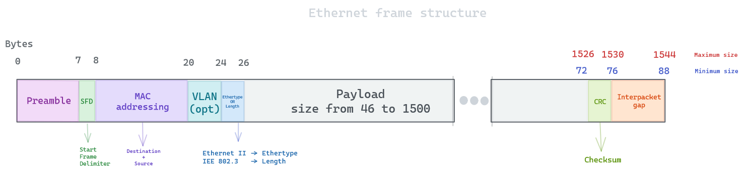
One notable frame structure of Ethernet frame is having no time-to-live field, which can lead to a switching loop (also known as broadcast storms). This can happen If there is more than one layer 2 path between two endpoints (connecting two ports on the same switch to each other), multicasts are then repeatedly forwarded forever, flooding the entire network. We will see how to avoid this in a later section.
While Ethernet frames are usually 1518 bytes long, they can potentially appear smaller or bigger depending on the system settings. A larger ethernet frame is called Jumbo frames and can go up to 9000 bytes long (or you can go further and beyond with Super jumbo frames going up to 64000 bytes). If this size is non-uniform to a network node, It will be detected as Jabber and subsequently dropped. On the opposite, an Ethernet frame has a minimum size of 64 bytes (18 bytes header and 46 bytes payload), anything smaller is considered Runt frames and is subsequently dropped.
You can probably notice there is multiple types of Ethernet frames, namely the one respecting IEEE 802.3 and Ethernet II. The main difference is IEEE 802.3 uses a LLC header that will be described later. Ethernet II type is largely more used in comparaison.
Wi-Fi 802.11
While we will not dive too deep into the 802.11 specifications, It is nice to compare it to Ethernet (wired) frames. They have different types of frames (control, management and data), we will just focus on the data frames. They are larger in size, but requires the use of a LLC header in the payload. It always starts with a frame control which contains the options of the wireless connection:

It uses MAC address, like Ethernet, but differ in their header definition:

Notice how similar It is to Ethernet, but allows for a bigger payload, since wireless devices are often battery powered, and they try to reduce the number of frames sent as It makes devices last longer.
Alternatives
In the data-link layer, while the IEEE 802 is often used, a few alternatives exist to perform the same function. It often depends on the network hardware used to transmit data on the physical layer.
Point-to-point
PPP is a data link layer communication protocol between two routers directly without any host or any other networking in between. It was designed to work with numerous network layer protocols such as IP or IPX. PPP is used over many types of physical networks such as phone line, ISDN. Your Internet Service Provider (ISP) could have used PPP to establish a connection through the facilities of the public switched telephone network.
It can provide authentication through password or challenge handshake, compression and error detection. It is often used whenever you need to tunnel data over IP networks, as a tunnel is by definition a point-to-point connection and PPP is thus a natural choice between the virtual network interfaces. PPP can assign IP addresses to these interfaces that can be used to route between the networks on both sides of the tunnel. These interfaces would be called tun0 or ppp0.
In case of VPN (e.g. IPSec in tunneling mode), no virtual network interfaces are created, since the tunnel is handled by the transport layer (TCP/IP), and L2TP is then used, but here PPP also provides IP addresses to the extremities of the tunnel.
ADCCP / HDLC
Previously used data link layer protocol which was bit oriented. they are both functionally equivalent, and most currently used protocols in the datalink layer were derived from their specifications. It was progressively less used due to Ethernet popularity.
LLC/MAC
The data link layer is often divided into two sublayers:
- Logical link control (LLC)
- Media access control (MAC)
LLC
The uppermost sublayer multiplexes protocols running at the top of the data link layer, It makes it possible for several network protocols to coexist within a multipoint network and to be transported over the same network medium. It also provides addressing and control of the data link. It can be considered as the interface between the network layer and the MAC. In short, the LLC provides a way for the upper layers to deal with any type of MAC layer.
It can also optionally provide flow control and error management capabilities, but It depends on the protocol stack, as It is usually taken care of by a transport layer such as TCP.
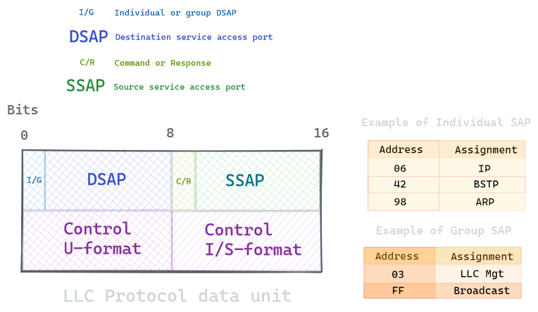
Note the control part can be either 8 or 16 bits long depending on the format (mostly 8 bits). We will not dive into the specifics, as It is rarely a source of bug, as you can see It is mainly to indicate the service access port.
This unit is then followed by a multiple of 8 bits, containing the information of the upper layer data.
But this model is rarely used in reality, and TCP/ARP frames will not use the SAP value for TCP/ARP, but will use SNAP instead. SNAP is an extension of the LLC, by adding 40 bits after the LLC header. SNAP supports identifying protocols by Ethernet type field values (Ethertypes); it also supports vendor-private protocol identifier spaces instead of being limited to the 7-bit identifying code.
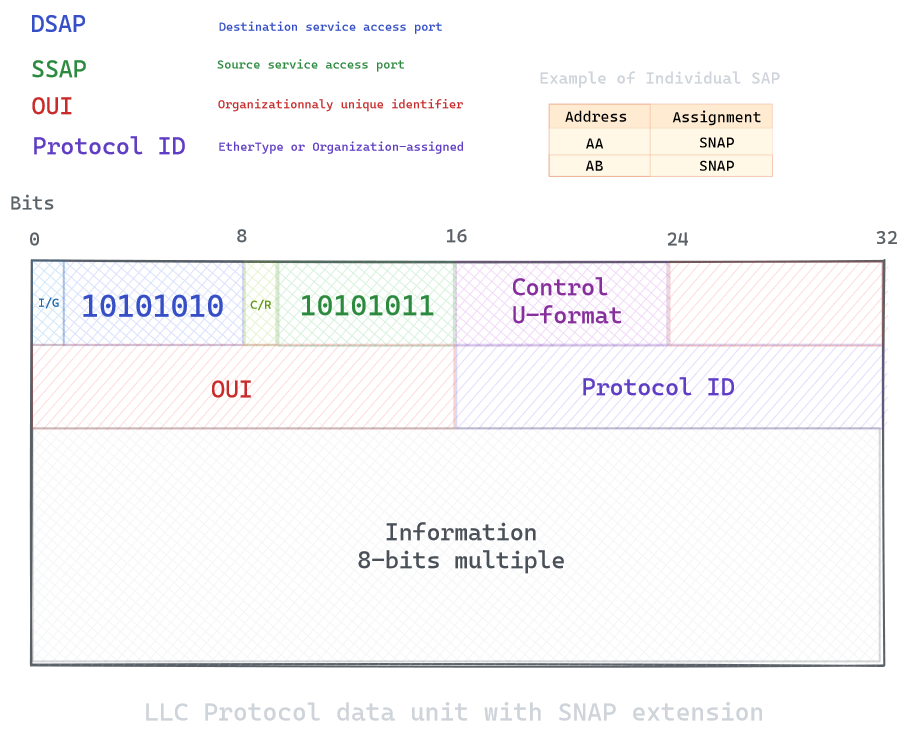
If the OUI value is zero, the protocol ID is the registered EtherType
An EtherType field in each frame is used by the operating system on the receiving station to select the appropriate protocol module (e.g., an Internet Protocol version such as IPv4). Ethernet frames are said to be self-identifying, because of the EtherType field. Self-identifying frames make it possible to intermix multiple protocols on the same physical network and allow a single computer to use multiple protocols together.
This is why, on Ethernet 802.3, the 8 octets (3 from LLC, 5 from SNAP) reduce the size of the available payload such as IP to 1492 bytes (from the default MTU 1500). Therefore, with protocols that have EtherType values, packets are usually transmitted with Ethernet II headers rather than with LLC and SNAP headers, but on other network types, the LLC and SNAP headers are required in order to multiplex different protocols on the link layer, as the MAC layer doesn’t possess an EtherType field, so there’s no alternative framing that would have a larger available payload.
For example, IP datagrams and ARP datagrams are transmitted over IEEE 802 networks using LLC and SNAP headers. But in reality, this specification is rarely followed, and most Ethernet frame will use Ethernet II, which include the Ethertype directly into the header, without any need for extension.
Ethernet II framing vs Ethernet 802.3 framing:
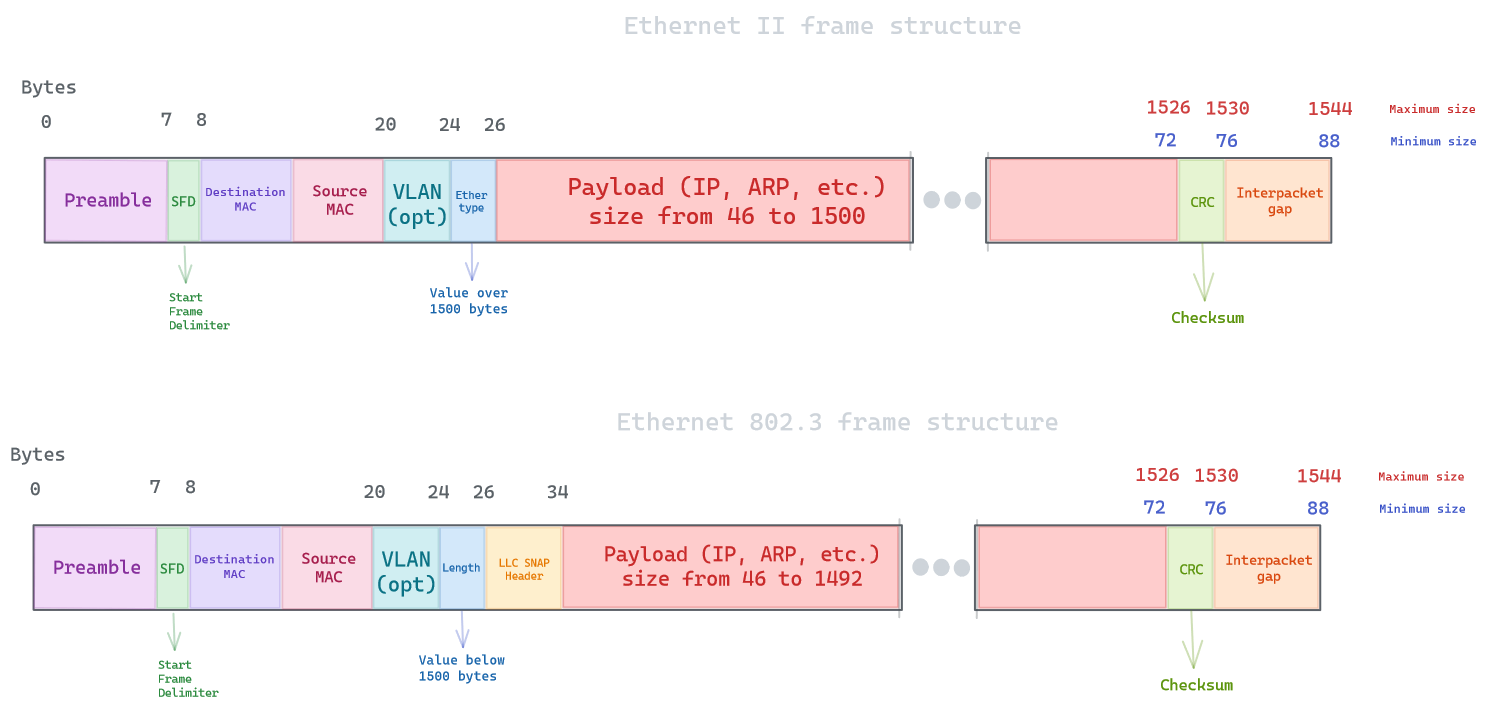
You can see how using Ethernet 802.3 frames reduce the payload size by the LLC+SNAP header, and overcomplicate things. This is why Ethernet II is here to stay, as It is less complicated and allow for a bigger payload. This also explains why Etherfield values are always over 1500 bytes in value. That value was chosen because the maximum length of the payload field of an Ethernet 802.3 frame is 1500 octets (0x05DC). Thus if the field’s value is greater than or equal to 1536, the frame must be an Ethernet II frame, with that field being a type field. If it’s less than or equal to 1500, it must be an IEEE 802.3 frame, with that field being a length field. Values between 1500 and 1536, exclusive, are undefined. This convention allows the coexistence of both standards on the same physical medium.
MAC layer
Also called the medium access control sublayer, It controls the hardware responsible for interaction with the transmission medium (wired, optical or wireless). While the LLC provides flow control and multiplexing for the logical link (EtherType, etc.), the MAC provides flow control and multiplexing for the transmission medium.
MAC access methods
In Ethernet, bit errors are very rare in wired networks, receiving incorrect packets will simply be detected and dropped, but not retransmitted (It will expect higher layer to do it). The collision detection is these case is handled by CSMA/CD, CD meaning Collision detection.
In Wireless communications, bit errors are very common, but the flow control and error management is handled by the MAC layer through CSMA/CA, CA meaning Collision Avoidance.
MAC addressing
It includes a local network address called MAC address, intended to be a unique serial number assigned by the network interface hardware (NIC) at the time of manufacture. It is 48 bits long, separated by colons every two digits
An example, this one belongs to Samsung Electronics:
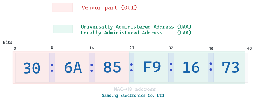
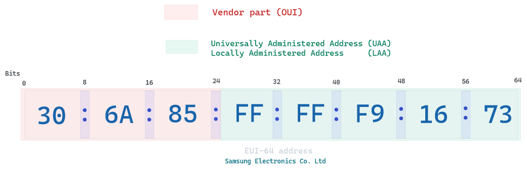
a MAC address can be defined universally by the manufacturer or locally by a system administrator. MAC address are by definition finite and we will end up running out of possible addresses, so an alternative called EUI was created. It simply adds 2 octets to the UAA, all MAC-48 are EUI by padding FF:FF between your OUI and UAA.
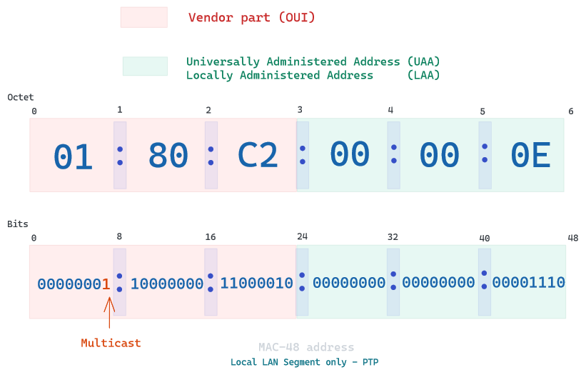
Ethernet frames with a value of 1 in the least-significant bit of the first octet of the destination MAC address are treated as multicast frames and are flooded to all points on the network.
Some blocks are reserved to specific usage, such as PTP (Time precision protocol) or STP (Spanning tree protocol), you can check them here. These blocks are either only on Local LAN link or either be forwarded through bridges.
Easier to understand with an example:
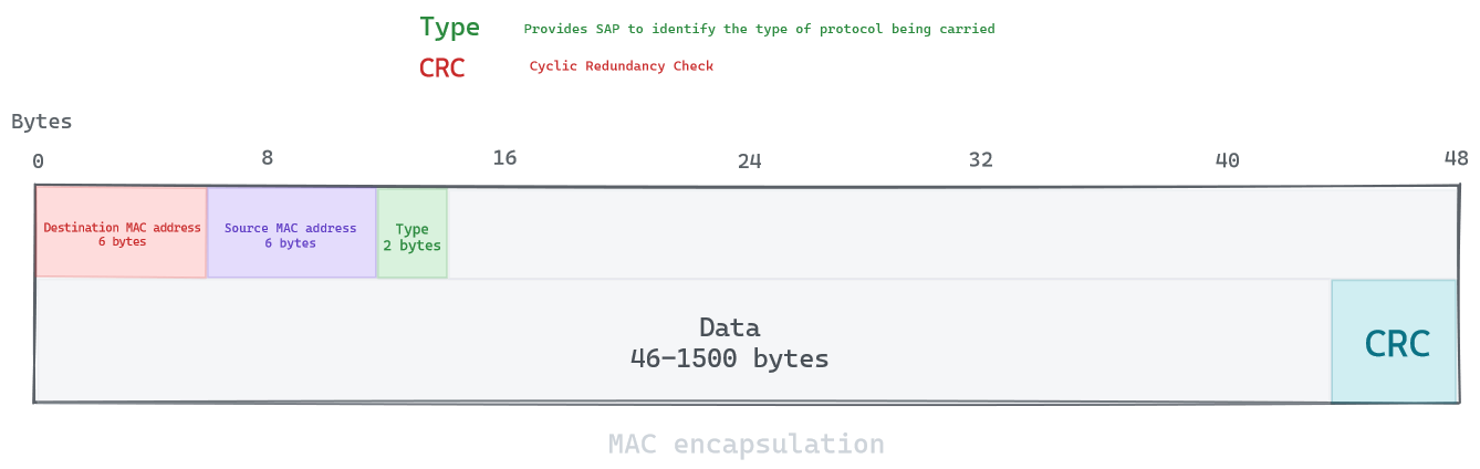
The MAC protocol is used to provide the data link layer of the communication protocol (e.g. Ethernet), and its header include 16 bytes with a CRC at the end:
Quality of service control
Also called Audio Video Bridging (AVB), It provides a set of technical standard to improve synchronization, low-latency and reliability for switched Ethernet networks. It is particulary useful in QoS applications requiring low jitter such as voIP and IPTV. This QoS is often implemented on the network/transport layer, but there is a few enhancements available on the datalink layer to implement it. These enhancements make use of the optional VLAN tag to implement priority values on data frames.
VLANs
A virtual LAN is any broadcast domain that is partitioned and isolated in a network at the data link layer. It works by applying tags to network frames to create the appearance and functionality of network traffic that is physically on a single network but acts as If It is split between separate networks. VLANs allow admins to group hosts together even if the hosts are not directly connected to the same network switch, greatly simplifying network design and deployment (less cables/devices).
An ethernet frame with a VLAN value is usually defined as tagged, and without the optional VLAN header, It is untagged. An Ethernet switch can decide to drop or forward tagged frames depending on its configuration (access or trunk mode, VLANs allowed, etc.).
This feature is one of the most used in modern networks, as you can scale multiple virtual switches inside one physical switch. Admins will use it to separate and isolate services, making the subnet size smaller (less broadcast noises) and more secure (easier to apply IPS/IDS/ACLs). Cloud providers are particulary fond of VLAN, as you can more easily scale your growing infrastructure.
Switch/Bridge/WAP
Speaking of VLANs direct us to the subject of Ethernet switch and bridges, and how they operate on the datalink layer.
Let’s start off with a hub, which is a network device without any logic implemented, It simply waits to receive incoming packets to blast it out on all other ports. It will cause network congestion due to the increased overhead and lots of Ethernet collisions (e.g. 6 hosts sending one packet each to a hub would result in creating 30 packets total on the network). This helps to understand why network devices need to implement some kind of logic to route packets efficiently.
The first network device to implement this logic on the datalink layer is the Ethernet switch. It uses the MAC destination address to forward a frame to the port associated with that address. Addresses are automatically learned by looking at the MAC source address on received frames. If a MAC address is unknown, It will simply flood the frame out to all its port but the ingress port, which will simply refresh its MAC address table.
A switch is stateless, so It has no memory on who requested which data, It does not operate on any upper layer protocols (IP, TCP, HTTP, etc.), It simply learn source addresses and forward by destination address. If you need to capture frames going from one port to another on a switch, you would use SPAN (i.e. port mirroring). However, this setup is limited and impacts your switch CPU. In reality people would prefer adding a network TAP (Terminal Access Point), which is a hardware device similar to a hub, but with 2 ports (port A and B) and a monitor port. They are non-obtrusive (they do not impact your ethernet switch), not detectable on the network, but usually come at a cost.
Now, if you understood what an ethernet switch is, you already know what an ethernet bridge is. The difference is simple, an ethernet switch is a multiport ethernet bridge. It simply relays Ethernet frames between devices connected to different ports, in bridge case, It would only be between two devices. Today, the term bridge and switch pretty much mean the same thing.
Historically, switches were a term used for devices working on the datalink layer, but It merged overtime with the term router, usually used for the network layer. Router includes the logic of the Internet Protocol which will be explained later, but this made switches capable of performing ARP requests to update its MAC address table. While switches were already sensitive to MAC flooding attacks, this also made them vulnerable to ARP spoofing.
As your network size grows, the number of switches (physical or virtual) goes up, up to thousands of bridges in some case. In order to provide the best route between two nodes, two features to be added onto an Ethernet switch:
- Redundancy (through STP)
- Load-balancing (through SPB)
LANs have traditionally relied on Spanning Tree Protocol (STP) and its variants (RSTP/MSTP) to prevent loop on the L2 layer. This topology is achieved by electring a root bridge and building a least-cost tree linking the root bridge with other non-root nodes. This least-cost tree is created by disabling all links which are not in the least-cost path towards the root. By being able to create a tree-like topology, we can also add more switches for redundancy without being threatened by a layer-2 loop.
While It prevents loop by forcing the path through the root bridge, It makes many links to remain unused, forcing sub-optimal paths. It showcases the limits of Ethernet networks, where all nodes in the LAN have to learn all end-device MAC addresses by flooding until the destination address is learned.
For example, imagine this topology:
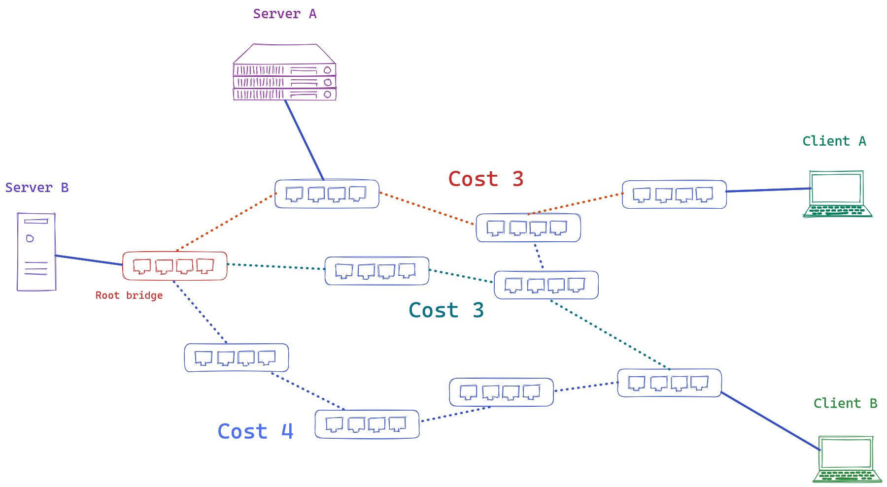
The forced path would be the least-cost ones going through the root bridge:

But It is not using all possibles paths, specially a potentially more efficient one:

SPB stands for Shortest Path Bridging, replacing older spanning tree protocols that blocked any redundant paths that could result in a broadcast storm. SPB allows all paths to be active with multiple equal cost paths, providing much larger layer 2 topologies, improving the efficiency by allowing traffic to load share across all paths of a mesh network. It is designed to virtually eliminate human error during configuration (which still happens today) and preserves the plug-and-play nature that established Ethernet as the de facto protocol at layer 2. It started being used since ~ 2014 (e.g. at the Winter Olympics).
A nice gif from wikipedia showcasing the algorithm:
Network layer
Now that we have understood how the data link layer is applied, we can move on onto the network layer. It is responsible for packet forwarding including routing through intermediate routers.
It is connectionless, a data packet can travel from a sender to a recipient without the need for an acknowledgement. Also, every host on the network must have a unique address that determines where it is. Networks also need to be able to forward message to other networks for wide-area communication, with the help of gateways or routers.
The main protocol of this layer is Internet Protocol or IP. It has the task of delivering packets from the source host to the destination host solely on the IP addresses in the packet headers. It is by definition an unreliable protocol, as It only ensures delivery on a best-effort basis, It does not guarantee that data will be delivered.
IPv4
Similar to the logic in other OSI layers, an IP packet consists of a header section followed by the data It encapsulates. One difference could be that It does not add a footer, so there is no data checksum for the packet, It is usually fine as the data link layer, through the CRC of Ethernet or FCS of 802.11 WLAN, can already detects most errors, and higher layers also adds data checksum (e.g. TCP for the transport layer).
An IPv4 header format looks like this:
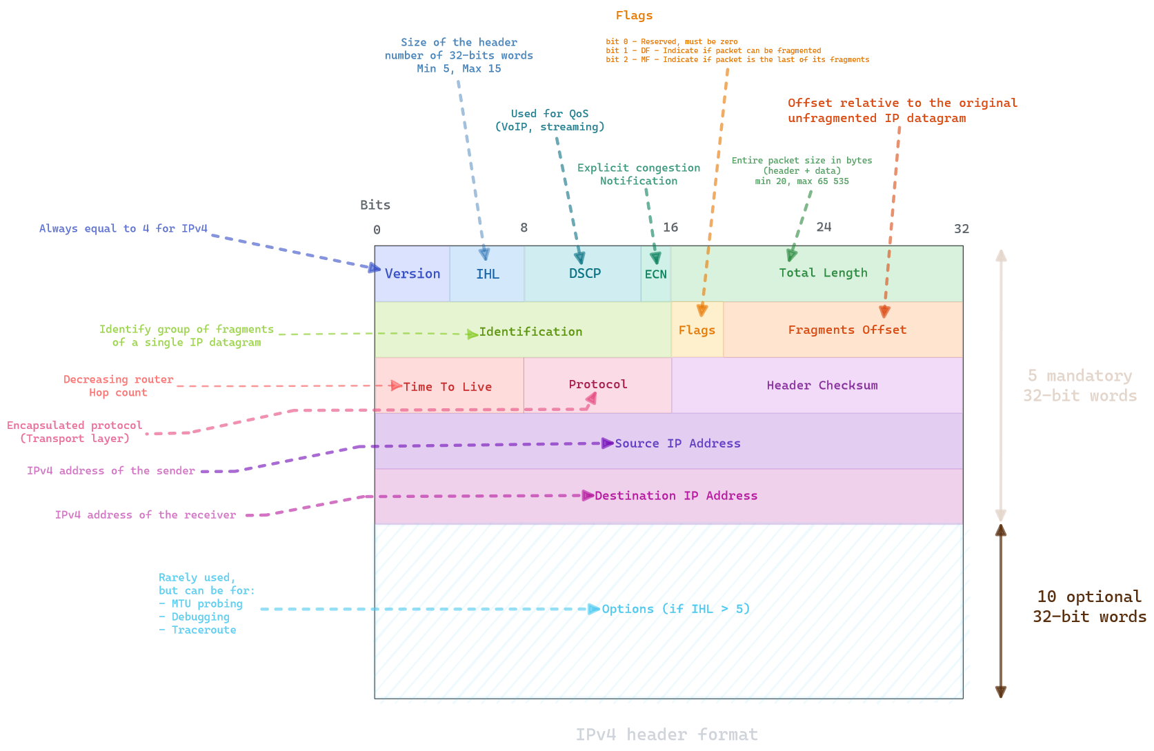
You can easily deduce from the different section that IPv4 is mainly used for encapsulating the higher layer, while allowing fragmentation and routing.
IPv4 address
The IP address space is 32-bit, allowing for 4 billions unique addresses, It is managed by the IANA and the regional Internet Registries (RIP NCC for Europe, ARIN for America). Each RIR maintains a publicly searchable whois database that provides information about IP address assignments.
For example, on a random European IP address:
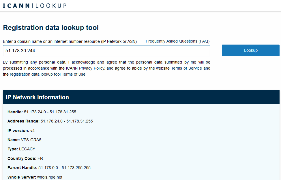
You can notice the IP is part of an address range, as those registries do not allocate IP one by one but block by block. Each block can be defined with a CIDR notation, which combines the address of its routing prefix in a compact format, in which the address is followed by a slash character (/) and the subnet mask.
Let’s say you wish to use 16 IP addresses in your network, you need to know two parts : your network identifier and the host identifier. This is done through a mask.
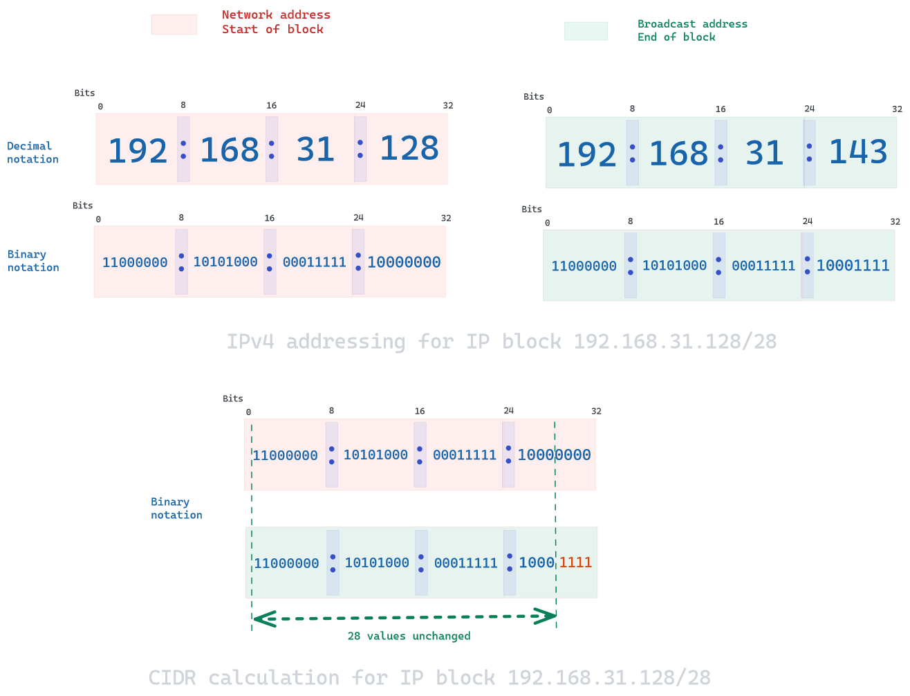
Here, the network identifier would be 192.168.31.128 (chosen randomly), and the IP block 192.168.31.128 - 192.168.31.143 ; notice how there is only 14 available address in the range, as the first one is network address, and the last one is the broadcast address. In CIDR notation, the mask would be /28 as there are 28 binary values that identify the network identifier. In reality, there would only be 13 available addresses, as you would need to count the gateway to route outside your network.
A few address block are reserved for special use, notably 127.0.0.0/8 for loopback addresses, 10.0.0.0/8 for local communication in VPNs or 224.0.0.0/4 for IP multicast. There is also three private networks block available, packets addresses in these ranges are not routable in the public Internet. These private hosts are notably used for desktop systems :
| CIDR block | Address range | Number of addresses |
|---|---|---|
| 10.0.0.0/8 | 10.0.0.0 - 10.255.255.255 | 16 777 216 |
| 172.16.0.0/12 | 172.16.0.0 - 172.31.255.255 | 1 048 576 |
| 192.168.0.0/16 | 192.168.0.0 - 192.168.255.255 | 65 536 |
Fragmentation and reassembly
The IP enables traffic between networks who are usually of diverse physical nature (no one has the same hardware), harnessing different transmission speed and MTU. When one network wants to transmit datagrams to a network with a smaller PDU, It may need to fragment its datagrams. This is done on the network layer by IPv4 routers.
This is only possible if a packet allows itself to be fragmented, as seen on the IPv4 flags header. At each fragmentation, 4 elements will require to be changed : length, flag, fragment offset and header checksum. One interesting feature is the possibility of fragmented packet to be re-fragmented thanks to the fragment offset being a 8-byte blocks multiple.
For example, imagine sending a 3320 bytes packet through this topology with different MTUs:
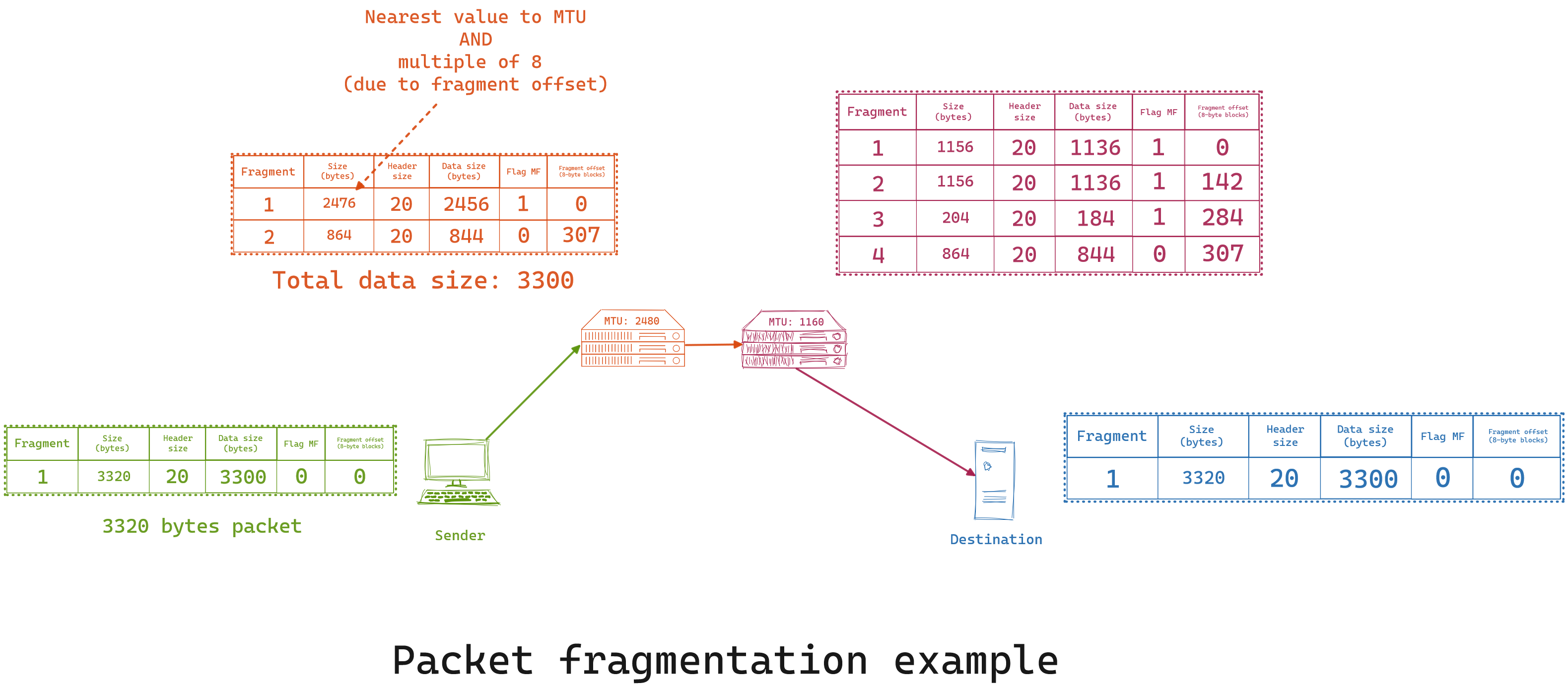
While this depend on some configuration, most routers will not re-assemble even if the sum of two fragments are under the MTU, and It will only be done once the packet arrives onto its destination.
ARP
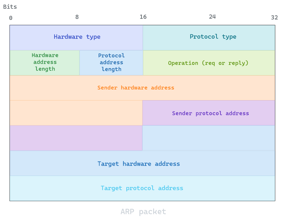
Now that we understand how IPv4 addressing and fragmentation works, we can try to understand how IPv4 address are linked to their lower layer address such as MAC. This specific resolution is done through ARP which is address resolution protocol. Since this protocol resolves layer 3 addresses with layer 2 addresses, It can be considered a link and network layer protocol.
The protocol uses a simple message format containing one address resolution request or response. The following example would be for IPv4 over Ethernet ARP packet, since hardware type (MAC) is 48 bits and protocol address (IPv4) is 16 bits. All systems retain an ARP cache table to avoid re-doing this request everytime.
ARP can also be used as an announcement protocol where a host can periodically broadcast a gratuitous ARP (GARP) message to announce its IP or MAC address change. It is usually done at startup, but will avoid flooding the network with those requests, as It could be considered ARP spoofing by malicious hosts.
IPv6
IPv6 is the most recent version of the Internet protocol. It was developped to deal with the long-anticipated issue of IPv4 address exhaustion. 4 billions devices is not a lot considering the world population and growing appetite for electronic devices such as smartphones. Today, IPv6 deployment is largely popular in higher population countries such as China or India, but most countries still largely use IPv4 in comparaison. It is deemed to be changed over the next few decades, as China announced plans to complete a national IPv6 rollout by 2030.
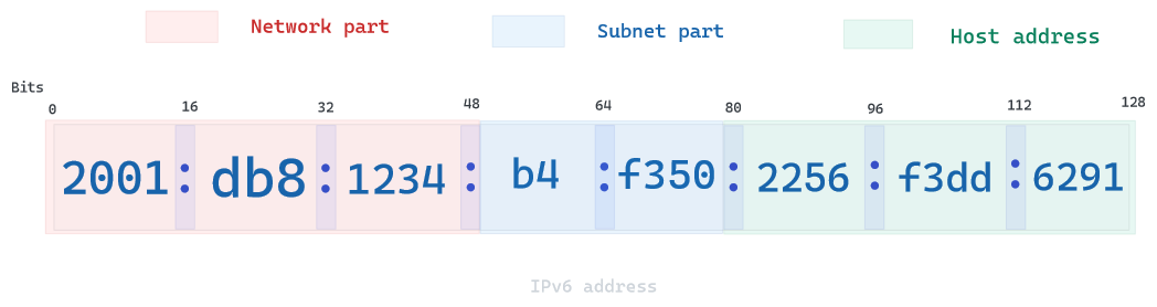
In IPv6, devices are assigned a unique IP address for identification and location definition. IPv6 uses 128-bit addresses, allowing around the same number of atoms available on Earth (e.g. pratically infinite).
IPv6 has a minimum packet size of 1280 bytes, consisting of 40-byte base header and 1240 bytes of payload.
IPv6 does not fragment its packets, as It uses Path MTU Discovery protocol to determine the network path between two hosts, this protocol is simply about activating the DF flag in IP header and record its path.
A few address types exist :
| Address type | Sub-type | Description | Example |
|---|---|---|---|
| Unicast | Global Unique address | Globally reachable by any host | 2001:581:f3d1:241f::/64 |
| Unicast | Link-local | Required on every interface, but packets cannot leave or enter the interface | fe80::/10 |
| Unicast | Loopback | Same as 127.0.0.1/8 in IPv4 | ::1/128 |
| Unicast | Unique local addresses | Equivalent to IPv4 private ranges | fc00::/7 |
| Multicast | Used to send a packet from one to many (always start with ff) | ff00::/8 | |
| Anycast | Used to send a packet from one to a group but only send to the first least expensive destination |
NDP
It shares the same function as ARP in IPv4. It uses five ICMPv6 packet types for the purpose of :
- Router solicitation
- Router advertisement
- Neighbor solicitation
- Neighbor advertisement
- Redirect
I will not describe the details, as we just to know It reproduces ARP function for MAC address resolution on IPv6.
ICMP
It is used by network devices to send error messages and operational information indicating success or failure when communicating with another IP address. It is always encapsulated in an IPv4 packet, so It is part of the transport layer.
For example, every device forwarding an IP datagram first decrements the TTL field in the IP header by one. If the resulting TTL is 0, the packet is discarded and an ICMP time exceeded in transit message is sent to the datagram’s source address. This is what the command traceroute essentially does.
A header format is defined as such:
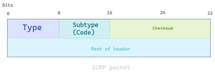
ICMP error messages contain a data section that includes a copy of the entire IPv4 header, plus the first eight bytes of data from the IPv4 packet that caused the error message. It can go up to 576 bytes in length.
A few examples of control messages types:
| Type value | Type | Subtype (code) | Description |
|---|---|---|---|
| 0 | Echo reply | 0 | Used to ping |
| 3 | Destination unreachable | 0 to 15 | Indicates the routing reason |
| 4 | Redirect message | 0 to 3 | Used for ToS or by network & host |
| 11 | Time exceeded | 0 to 1 | Reassembly or TTL expiration |
| 12 | Bad IP header | 0 to 2 | Missing parameter or option, wrong computation in IPv4 header |
Some routers do not allow ICMP message to pass through due to security reason as It can be used to probe your network, but It is most often used for debugging and troubleshooting reason.
Nat / Masquerade
Network address ranslation (NAT) is a method of mapping an IP address space into another by modifying network address information in the IP header of the packets while they are in transit across a traffic routing device.
It has become an essential tool in conserving global address space in the face of IPv4 address exhaustion. In fact, one Internet-routable IP address of a NAT gateway can be used for an entire private network.
There is two types of NAT operations:
- Destination-based (DNAT)
- Source-based (SNAT)
:triangular_flag_on_post: For some vendors, SNAT can also mean stateful (e.g. Cisco) or secure (e.g. F5 Networks or Microsoft)
DNAT
Destination network address translation is a technique for transparently changing the destination IP address of a routed packet and performing the inverse function for any replies. Any router situated between two endpoints can perform this transformation, and It is commonly used to publish a service located in a private network on a publicly accessible IP address. This use is also called port forwarding or DMZ when used on an entire server. If you wish to protect your server behind a firewall, this is a needed feature.
SNAT
Also called One-to-Many NAT, It is a technique used for transparently changing the source IP address of a routed packet and performing the inverse function for any replies. The majority of network address translators map multiple private hosts to one publicly exposed IP address. The way It works is a router in that network has a private address of that address space. The router is also connected to the Internet with a public address.
As traffic passes from the local network to the Internet, the source address in each packet is translated on the fly from a private address to the public address. The router tracks basic data about each active connection (particularly the destination address and port). When a reply returns to the router, it uses the connection tracking data it stored during the outbound phase to determine the private address on the internal network to which to forward the reply.
To logic works well for one-to-one conversion, but in order to map multiple address (one-to-many), a feature called masquerade is needed. It allows all of the hosts on a private network to use the Internet at the price of a single IP address. The word masquerade comes from a party or dance where people wear masks, and It pretty much defines the logic behind it.

Using Masquerade today is a must, as It also forbid external network to access any of your private network since none of the hosts on the supported network behind the router are ever directly seen, and lays the foundation for applying security measures to your private hosts. It comes at a cost, since It requires CPU ressources for the translation and forbid you from hosting services relying on incoming sessions to work (such as FTP).
OSPF
To end the presentation of the network layer, we can talk about the Open Shortest Path First (OSPF) routing protocol used for IP networks. It is widely used in large enterprise networks and large service provider as the de-facto protocol in a single routing domain. It is part of Interior gateway protocol (IGP), alternatives are RIP or IS-IS.
It gathers link state information from available routers and constructs a topology map of the network. The topology is then used to routes packets based solely on their destination IP address. OSPF detects changes, such as link failures, and converges on a new loop-free routing structure within seconds. It computes the shortest-path tree for each route based on Dijkstra’s algorithm.
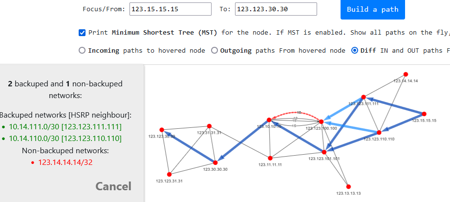
OSPF uses multicast addressing for distributing route information within a broadcast domain to all IP routers but without traversing them.
You can try it out here, for example:
Useful commands and utilities
I will be using a CentOS 9 Stream which came out in late 2021, some commands might differ depending on the Linux distribution you use, but the way It works will remain mostly the same.
IP command
Your main tool out of the box will be the ip command, It is a recent command, and people often still uses ifconfig instead. ip utility regroups many tools into one single command, such as arp, route, ifconfig, netstat. If you use it in scripts, make sure the command is installed !
I created some hosts in a private LAN, and have them able to access the Internet, check out the PFSense article for more details
First, let’s show our network interface with ip link

We could even print statistics on their use with the -s argument:
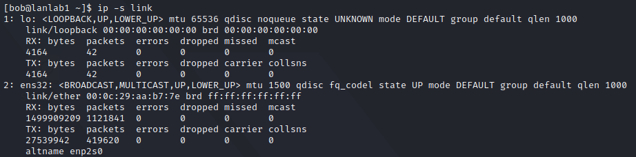
This command will show you the linklayer interfaces, and thus only the MAC addresses for each device, they show you the main characterics, which is mainly about :
- Device enabled and connected (e.g. UP and LOWER_UP respectively)
- The device capability (BROADCAST, MULTICAST)
- Available MTU (notice the loopback higher MTU as It is in memory only, this value was bumped up in 2012)
- Some QoS values
- the assigned MAC value and its broadcast
We can even use it to bring our device down with ip link set <interface> up/down

But It requires sudo-access since It could potentially impact others users.
Now, let’s move onto the network layer, and show our IP address with ip address
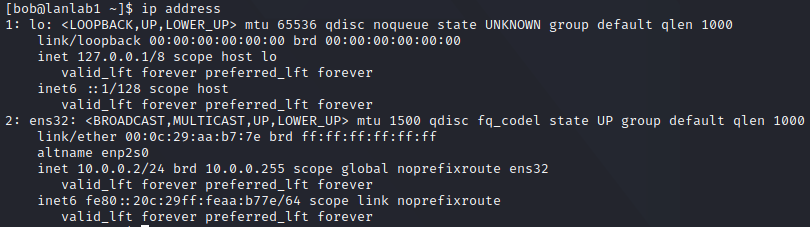
Notice how the command returns the linklayer informations, and then an IPv4 and IPv6 address. You can see the loopback address being 127.0.0.1/8 and ::1/128, but more interestingly, the ens32 device has a private IPv4 address (private block 10.x.x.x) and link-local IPv6 address (starts with fe80::).
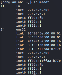
The utility also allows us to check the multicast address available with ip maddr:
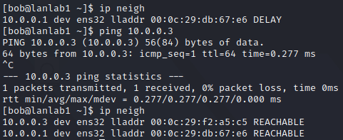
And our local ARP table with ip neigh, which is empty at first, but get filled as we start discussing with others hosts on LAN:
The command ip route can also be used to print our routing table, used by our host to route packets on the network:

Here you can see two simple rule which says:
- route everything by default to our gateway located on 10.0.0.1 through ens32 network interface
- Anything directed onto the private IP block 10.0.0.0/24 can be reached on device ens32 with IPv4 source address 10.0.0.2
These rules are applied from the top and then goes down, and If It doesn’t match any rule, It simply get dropped. You can notice that since the default rule is first, the second one will never be applied.
While this is not dependent on the layer 2 or 3, you can also use ss to show your host services open to the network

/etc
Most networks configuration are located in /etc, but the exact files are not always the same depending on your distribution.
One of the most common interface file is /etc/sysconfig/network-scripts/ but here mine is empty:

But I can definitely see some network interfaces defined in /etc/networks

In my distribution, those settings are done through NetworkManager and located in /etc/NetworkManager/system-connections
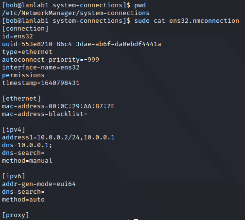
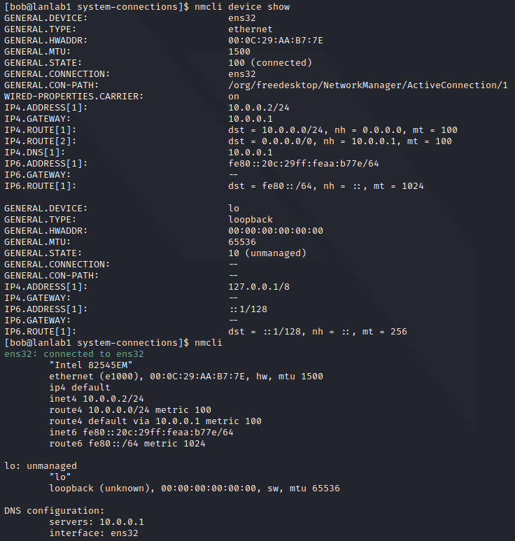
You can use nmcli to interact with it
/proc
A lot of informations about your configuration can also be accessed directly onto /proc/net
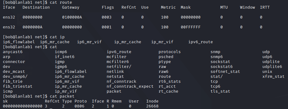
You focus on accessing process specific statistics, such as the ARP_cache:

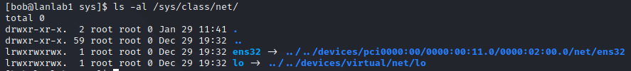
/sys
You can also access the /sys directory for more device related informations, a simple search can help us where to look for:
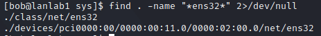
Which allows us to check ens32 configuration:
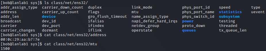
Which was a symbolic link to our hardware device definition:
Conclusion
We have seen how the linklayer uses frame to transport data across a physical medium, and how It encapsulates its data thanks to MAC addressing. This allows the network layer to use IP for fragmentation and global addressing on a wider variety of networks. While IPv4 and IPv6 can be different in the way they work, they share the same idea of providing a unique address for a device across the globe. A lot was to cover, between ethernet/wifi frames, IP addresses and its link to MAC through ARP, and how NAT try to cover the problem of IP exhaustion. A few commands allows you to handle this on your host, and they are usually vital for people to learn whenever they create a new host, as they are your gateway to the entire Internet.
Not everything was explained, and if you wish to focus your attention on a specific subject, check out the links below for more information.
Credits
https://en.wikipedia.org/wiki/Subnetwork_Access_Protocol
https://networkengineering.stackexchange.com/questions/732/introductory-level-explanation-of-vlans
https://www.al-enterprise.com/-/media/assets/internet/documents/spb-architecture-tech-brief-en.pdf
https://www.redhat.com/sysadmin/what-you-need-know-about-ipv6
https://www.oreilly.com/openbook/linag2/book/ch11.html
https://access.redhat.com/sites/default/files/attachments/rh_ip_command_cheatsheet_1214_jcs_print.pdf